Open Source 555 Timer
Introduction
In this post, I’ll share how I designed, laid out, and manufactured my own analog chip using open-source tools for a total cost of only $210.
Design
For schematic capture I used Xschem. To learn the tool I was able to find video tutorials on YouTube. I found B. Minch’s tutorials really useful and I referenced the Xschem Manual quite a bit as well.
The below figure is the actual schematic of the original CMOS 555 timer, published by the creator himself, the late Hans Camenzind. His book is free online.

I wanted to do my own version though, and since unlike in Hans’ era I don’t need to save on cost-per-transistor or worry about cutting Rubylith by hand, my comparators used a few extra transistors.
Xschem supports hierarchical design, and aside from the resistors and discharge FET, I put everything else inside of its own level of hierarchy.
I implemented the comparator using a positive feedback decision circuit sized to provide some hysteresis and I used three 10k resistors to generate the reference voltages. (So perhaps I should refer to this open source version as a 10-10-10 Timer).
I sized a large NFET as a discharge device, and I put some additional tapered inverters between the SR latch and the discharge FET.
I designed my own logic cells, including the inverters and SR latch, but the Skywater PDK does come with a standard cell library that I haven’t looked into yet.

Simulation
For simulation I used NG SPICE. Again, YouTube for simulation tutorials is really useful, but don’t be afraid to reference the NG Spice Manual too. I used it a lot, and was able to find examples of what I needed by searching with CTRL + F.
I built a top-level symbol and wired up a testbench where I configured the timer in astable mode.
I wanted to test out Monte Carlo simulation. With B. Minch’s excellent YouTube tutorials I was able to figure it out.
Here is a histogram plotting the measured frequency at TYP:

To get more practice using the tools, I also measured the spread in offset voltage and hysteresis of just the comparator in another Monte Carlo test bench shown below.

Although I have plotted a Gaussian curve over top of both plots, the offset voltage looks bimodal, and the hysteresis plot is right skewed. Interesting, and I might have to make a follow up post to discuss why this is later.
I think it’s pretty cool to have Monte Carlo simulation working with open source tools! It takes a bit of setting up and is not GUI driven but it’s not too hard, and once you get everything set up once its easy to copy for future testbenches.
Layout
For layout I used Magic. I found this tutorial the most useful for learning how to use the tool.

I followed Tim’s layout style, using full guard rings for all analog devices.
I laid out the comparator input-pair in a common-centroid fashion, which you can see annotated on the layout below.

I used wide metal for VDD and VSS. I copied Tim’s method of “filling” out VSS metal in the local interconnect level between guard rings. I thought his style made for a really clean analog layout.
The total area of my design was about 45um x 40um.
LVS
For LVS I used Netgen. I recommend reading the tutorials on Tim’s site for this one.
Extraction
I extracted an RC netlist from the layout and created the below testbench. I put an instance of the schematic-only version of the timer next to the RC extracted version of the timer.
I ran a simulation to compare the resulting frequency from each.
The top waveforms are the output from the extracted version.
The bottom waveforms are the output from the schematic version.
Highlighted in yellow are the result of a .MEASURE statement used to measure the time high, time low, and total frequency of each.
You can see that the observed difference in frequency is about 50Hz. Close, but not zero!
The extraction tool lets you extract R-only, C-only, or RC. The results below are for the RC version. It would be interesting to see if this error is present in the R-only or C-only versions.


Testing
I used Tiny Tapeout to manufacture my chip. For $210.00 including shipping they sent me one packaged IC in a QFN mounted on a test PCB shown below:

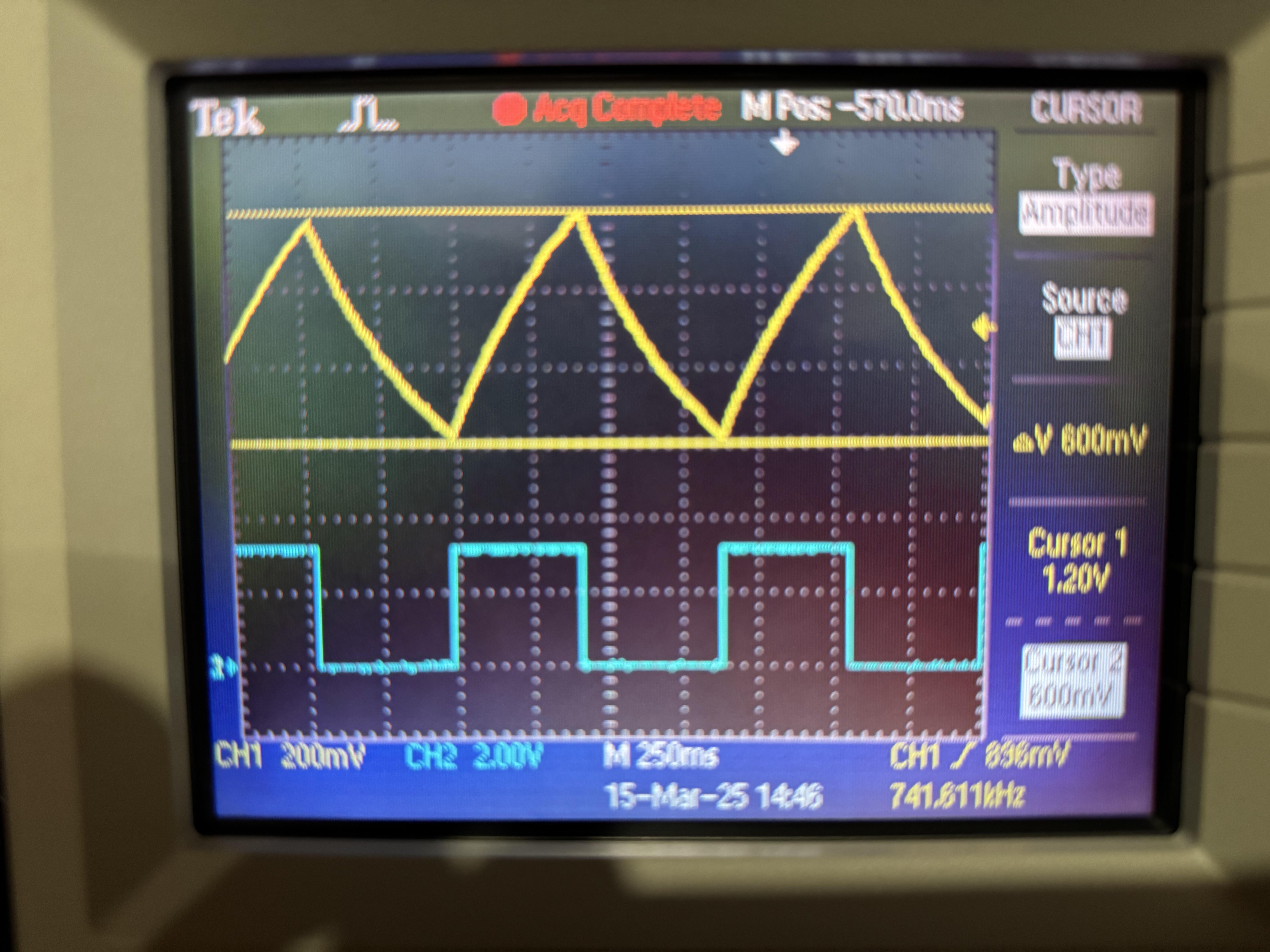
I wired up the 555 in astable mode with a frequency low enough for some good LED blinking. The below scope shot shows the comparator switching at 600mV and 1.2V:
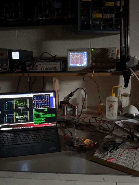
Full lab setup below comparing schematic, RC extracted, and bench-top results:
Matt Venn - creator of Tiny Tapeout - put together this video of his bench top testing of the 555.
Conclusion
Carl Sagan once said, “To bake an apple pie from scratch you must first create the universe”.
And I say, to blink an LED from scratch, creating your own chip is going far enough.